Engineering · Cat ladders
18m Cat Ladder Design Engineering Singapore
Engineering decisions that go into specifying, calculating, drawing and endorsing an 18m fixed vertical ladder for Singapore industrial projects — with reference to BS EN ISO 14122-4 and Singapore practice.
· By Ezzogenics
Why 18 metres is a watershed height
A cat ladder of 3–6 m is essentially a maintenance prop: easy to specify, easy to install, easy to certify. At 18 m total climb, the design problem multiplies in three directions simultaneously:
- Climber fatigue and fall-arrest physics — a single uninterrupted vertical climb beyond ~6 m is unsafe even for fit users. EN ISO 14122-4 and OSHA both demand staged climbs with rest landings.
- Buckling and dynamic deflection — a slender 18 m steel column wants to whip laterally. Stiffness, not strength, drives stile sizing.
- Anchorage demand — 18 m of self-weight + climber + wind load + fall-arrest reaction transmits into wall fixings that must each take 5–10 kN repeatedly over a 25-year life.
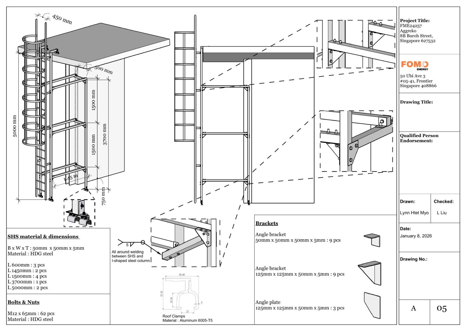
The reference project for this blog is the Aggreko / 8B Buroh Street cat ladder — designed by DWB CS-Engineering Consultants, fabricated in Aluminium AA 6063-T6, with a middle landing platform, full safety cage, and chemical-anchor wall fixings. The QP report runs 133 pages of STAAD.Pro analysis to clear a single ~8.6 m ladder for endorsement under the Singapore Building Control Act. Scaling that thinking to 18 m is what this blog is about.
1. Anatomy of an 18 m cat ladder
An 18 m cat ladder is never one continuous run. It is a stack of three 6 m flights (or two 9 m flights with a single mid-rest), separated by rest platforms / landing platforms. A typical layout:
  ── Roof exit hand-grab + transition barrier ──
  ┃                                              ┃
  ┃  Top flight  6,000 mm                        ┃
  ┃                                              ┃
  ── Upper rest platform (≥ 700 × 700 mm) ──────
  ┃                                              ┃
  ┃  Middle flight  6,000 mm — flights staggered ┃
  ┃                                              ┃
  ── Lower rest platform (≥ 700 × 700 mm) ──────
  ┃                                              ┃
  ┃  Bottom flight  6,000 mm                     ┃
  ┃                                              ┃
  ── Floor / grade level + retractable section ──
Why staggered flights? EN ISO 14122-4 §4.4.2.2 requires that if a climber falls, the fall is intercepted at the rest platform within ≤ 6 m — a continuous straight 18 m drop is not survivable even with a fall arrester. Modern designs offset adjacent flights laterally by ≥ 300 mm so that a fall ends on the platform edge, not the rung below.
Standard component sizes (taken directly from the Buroh Street drawings, scaled):
| Element | Specification used | Reference |
|---|---|---|
| Stile / stringer | 70 × 30 × 3 mm aluminium C-channel (AA 6063-T6) | DWB CS-Engineering report |
| Rung | 25 mm Ø aluminium round bar, non-slip top coating | EN 14122-4 §5.2.2.4 (≥ 20 mm flat tread) |
| Rung pitch | 300 mm constant | EN 14122-4 §5.2.2.2 (225–300 mm) |
| Cage hoop | 75 × 6 mm aluminium flat bar horizontal, 50 × 6 mm vertical | OSHA / EN cage geometry |
| Wall bracket | 75 × 75 × 6 mm hollow section + 75 × 50 × 3 mm gusseted bracket support | Buroh St drawings |
| Bearing plate | 210 × 210 × 10 mm (mid-rest), 200 × 200 × 10 mm (intermediate), 100 × 150 × 10 mm (single-anchor) | Buroh St drawings |
| Anchors | 4 × Hilti HST3-R M12 / Hilti HIT-RE 500 V4 with M12 rod, embedment ≥ 110 mm | EN 1992-4 + Hilti ETA |
| Bolts/nuts | Stainless A4 / SS304 M8–M16 | Drawing notes |
| Roof clamp | Aluminium 6005-T5 (Aggreko design) | Drawing notes |
2. The design loads to satisfy
For an 18 m ladder serving an industrial roof in Singapore, the QP must run loads from four codes simultaneously:
| Load | Source | Magnitude |
|---|---|---|
| Self-weight (dead) | EC0 / SS EN 1990 | 78.5 kN/m³ steel · 27 kN/m³ aluminium |
| Climber rung load F1 | EN ISO 14122-4 §5.1 | 1.5 kN per rung, 100 mm wide footprint, anywhere |
| Climber stile load F2 | EN ISO 14122-4 §5.1 | 1.5 kN per stile, two locations 2 m apart |
| Platform live load | EC1 / SS EN 1991-1-1 | 1.5 kN/m² + concentrated 1.5 kN per person |
| Wind load | SS EN 1991-1-4 + NA Singapore | 0.80 kN/m² (Buroh St report value) |
| Fall-arrester reaction | EN ISO 14122-4 §5.7 | ≥ 6 kN at top anchor |
| SCDF storey-shelter shock | SCDF Cl. 2.11 (if applicable) | 12.5 g in all directions |
These are characteristic loads. The QP applies partial factors per EC0:
- γG = 1.35 for permanent (dead)
- γQ = 1.50 for variable (climber, wind)
- γM0 = 1.00 for steel bending; γM1 = 1.10 for aluminium and stainless (lower stiffness materials)
The Buroh Street report explicitly cites:
"EC0 – Eurocode 0 SS EN 1990 & NA – Basis of Structural design; EC1 – SS EN 1991-1-1 & NA; EC3 – SS EN 1993-1-1 & NA"
For an 18 m ladder this is the non-negotiable code stack.
3. The structural model — what an 18 m STAAD.Pro run looks like
The Buroh St QP modelled an 8.6 m ladder in STAAD.Pro V8i with:
- 205 nodes
- ~200 frame elements (one per rung + stiles + cage hoops + brackets)
- Multiple load cases combined per EC0 fundamental combination
Scaled to 18 m, you would expect:
- ~430 nodes
- ~430 elements
- 2 staggered rest platforms modelled as horizontal frames
- 8–12 wall-anchor points (4 per platform + 4 per top/bottom)
Critical model details
(a) Boundary conditions
- Wall brackets are modelled as fixed in 3 translations, free in 3 rotations (pinned to the wall plate). Some QPs model them as fully fixed (rigid moment connection) — this overestimates capacity. The Buroh St report uses pin-fixed which is the conservative and correct approach.
(b) Stile-rung joints
- All rungs are welded (3 mm fillet weld all round, per general note 6 of the drawings). Modelled as rigid in the frame analysis.
(c) Cage as a structural element?
- Most QPs exclude the cage from primary structural action — it is treated as fall-arrest hardware only, and the stiles must take 100% of the climber load. This is the safe assumption.
(d) Buckling
- For aluminium stiles 6 m long, slenderness λ = L/i ≈ 6000 / 11 ≈ 545, which is far above the EC9 limit (λmax = 200 for compression members). Lateral restraint at every rung is what makes the assumption work — the rung-to-stile welds force buckling to occur over a 300 mm rung pitch, not 6 m.
4. Worked utilisation check on the stile
Using the Buroh Street section (70 × 30 × 3 mm aluminium C-channel, AA 6063-T6, fy = 190 N/mm²) over a 300 mm rung-to-rung span:
Section properties (C-channel 70 × 30 × 3):
- Area A = 270 mm²
- I (strong axis) = 8.6 cm⁴ ≈ 86,000 mm⁴
- Wel (strong axis) = 2.46 cm³ = 2,460 mm³
Design moment from F1 = 1.5 kN at mid-rung (treating stile as continuous beam):
\[ M_{Ed} = \frac{F_1 \cdot L}{8} = \frac{1.5 \cdot 0.300}{8} = 0.056 \text{ kN·m} = 56 \text{ N·m} \]
Design bending resistance (γM1 = 1.10 for aluminium):
\[ M_{Rd} = \frac{f_y \cdot W_{el}}{\gamma_{M1}} = \frac{190 \cdot 2{,}460}{1.10} = 425 \text{ N·m} \]
Utilisation: M_Ed / M_Rd = 56 / 425 = 13% ✓ — comfortable for the rung-to-rung span.
Now check the stile between brackets — 1,500 mm bracket spacing, F2 = 1.5 kN at mid-span:
\[ M_{Ed} = \frac{F_2 \cdot L}{4} = \frac{1.5 \cdot 1.500}{4} = 0.563 \text{ kN·m} = 563 \text{ N·m} \]
Utilisation: 563 / 425 = 132% ✗ — fails if no intermediate restraint.
That is exactly why the 18 m design needs brackets at ≤ 1.5 m spacing, and ideally ≤ 1.0 m for aluminium (because of the lower modulus E = 69 GPa vs 210 GPa for steel). A "skinny" aluminium ladder with sparse brackets is the most common QP rejection reason in Singapore submissions.
The Aggreko drawing addresses this by specifying brackets at 1.45 m, 1.50 m intervals — and that drawing is for a 5 m ladder. For 18 m the bracket pitch would need to drop further or the stile section sized up to 70 × 30 × 4 mm or even a closed SHS 50 × 50 × 4 mm for the longest spans.
5. The wall connection — the highest-failure subsystem
Every cat-ladder forensic report points to the same conclusion: the wall fixings are the failure-prone subsystem, not the ladder itself. The Buroh Street commenting reviewer flagged exactly this — visible on Sheet 5 of the COMMENTS PDF:
- "BOLT (M16) DIAMETER NOT MENTIONED" — drawing didn't specify the rod diameter for the chemical anchor
- "EMBEDMENT 85 mm" — flagged as inadequate for M16 chemical anchor (rule of thumb is 8d = 128 mm for M16)
- "NOT TALLY" — bracket detail and assembly view didn't match
- "SUPPORT MISSING" — the warehouse front elevation showed an unsupported run
- "NOT TALLY PLS UPDATE" — section dimensions inconsistent across sheets
These are the five most common reviewer comments on cat-ladder submissions in Singapore, and at 18 m every one of them becomes a structural defect rather than a paperwork fix.
Anchor design for an 18 m ladder
A representative bracket on an 18 m ladder might carry:
| Action | Value |
|---|---|
| Climber tension via lever arm (200 mm projection) | 1.5 kN × 200/120 = 2.5 kN |
| Self-weight share of one stile | 0.4 kN |
| Wind on one bracket area | 0.8 kN/m² × 0.5 m² = 0.4 kN |
| Fall-arrester impact (top bracket only, factored) | 6 kN characteristic → 9 kN design |
| Total tension at top bracket (factored) | ≈ 12 kN |
For a Hilti HIT-RE 500 V4 + M12 stainless threaded rod in C25/30 cracked concrete with hef = 110 mm and edge distance c1 = 150 mm, the ETA-tabulated tension capacity is approximately 15–20 kN — comfortable. But drop to M10 with hef = 80 mm (the embedment shown on the Buroh St drawing) and capacity falls to roughly 6–8 kN — failing the top-bracket case.
This is precisely why the reviewer flagged the 85 mm embedment. For 18 m ladders the rule is: M12 minimum rod, hef ≥ 110 mm, ETA Option 1 cracked-concrete approval, A4 stainless rod for outdoor.
6. The middle landing platform — design specifics
The Buroh St ladder includes a single middle landing platform, configured as a 740 mm Ø circular platform inside the safety cage. Detail callouts include:
- 75 × 75 × 6 mm SHS as primary platform frame
- 38 × 38 × 6 mm angle bar as in-fill
- 50 × 75 × 3 mm hollow section as platform support to the wall
- 6 mm thick galvanised mesh wire as tread / fall-through protection
- Hand-grabs continuing through the platform per EN 14122-4 §5.6
For an 18 m ladder you need at least two such platforms (one every 6 m or every 12 m if a fall arrester is fitted, per EN 14122-4 §4.4.2.4):
| Climbing height | Required platforms |
|---|---|
| H ≤ 6 m | None (single flight) |
| 6 m < H ≤ 12 m | One platform |
| 12 m < H ≤ 18 m | Two platforms |
| H > 18 m | Three or more |
Design loads for each platform:
- 1.5 kN/m² distributed (EC1) — standard floor live load
- 1.5 kN concentrated per person at the unfavourable corner
- Same fall-arrester reaction at the upper-flight start anchor
7. Geometry, clearances and OSHA-compatible layout
Per EN ISO 14122-4 (most-cited values for a Singapore submission):
| Parameter | Value | Clause |
|---|---|---|
| Rung pitch (constant) | 225–300 mm | §5.2.2.2 |
| Tread surface flat width | ≥ 20 mm | §5.2.2.4 |
| Clear width between stile and slip-protection | 150–250 mm | §5.2.2.3 |
| Clearance in front of rung | ≥ 650 mm (≥ 600 mm at obstacles) | §4.4.1 |
| Clearance behind rung | ≥ 200 mm (≥ 150 mm at obstacles) | §4.4.1 |
| Cage from rung centreline | 700–800 mm | §5.5 |
| Cage hoop pitch | ≤ 1500 mm | §5.5 |
| Top-rung exit gap | 60–75 mm to landing | §4.5 |
| Fall-arrester required from | ≥ 3 m climbing height | §4.4.2.2 |
| Single-flight max length | 6 m | §4.4.2.3 |
| Rest platform interval (with arrester) | ≤ 12 m | §4.4.2.4 |
The Aggreko drawing dimensions (1450 mm cage projection, 750 mm cage standoff, 5000 mm flight, 450 mm exit width) all sit safely inside these envelopes.
8. The QP submission package — what 18 m takes
A submission to BCA/SCDF for an 18 m cat ladder under Section 5A of the Building Control Act typically includes:
- Architectural drawings — front elevation, side elevation, plan, all with key dimensions
- Structural drawings — bracket details, weld details, anchor bolt schedule, bearing plate sizes
- Material schedule — every bar size, grade, finish, fastener spec
- Design report — typically 80–150 pages:
- Introduction & code references
- Design loadings (dead, live, wind, climber, arrester)
- Material strengths
- STAAD.Pro 3D model output (geometry, load cases, member forces, deflections)
- Stile bending check at most onerous span
- Bracket utilisation check (welded connection capacity)
- Anchor design per EN 1992-4 / Hilti PROFIS / Fischer FiXperience output
- Deflection check — typically L/200 for industrial access ladders
- Wind / dynamic check if H > 12 m
- PE endorsement — name, registration number, signature, date, declaration that the design complies with the Building Control Act
- Site test results — anchor proof-load tests at 1.5 × design tension per BS 8539, signed test sheets
The Buroh Street files in workspace illustrate this exactly: a separate 133-page warehouse design report (20260225-QP-REPORT-FOR-CAT-LADDER-WAREHOUSE-For-Buroh-Street-ENDORSED.pdf) plus a drawing set with a reviewer's mark-up PDF (20260223-Buroh-St-Cat-ladder-COMMENTS.pdf) — and at this scale the workflow is draw → STAAD model → calc report → PE endorse → reviewer comments → revise → re-endorse → BCA submission.
9. Common failure modes the QP must catch
| # | Failure mode | Mitigation |
|---|---|---|
| 1 | Stile buckling between widely-spaced brackets | Bracket pitch ≤ 1.5 m for steel, ≤ 1.0 m for aluminium |
| 2 | Anchor pull-out from inadequate embedment | hef ≥ 8d (e.g. 96 mm for M12); use ETA Option 1 cracked-concrete chemical anchor |
| 3 | Galvanic corrosion at aluminium-steel anchor interface | Stainless A4 fasteners only; isolating washer if mixed |
| 4 | Single-anchor bracket levering off | Always 4 anchors per bearing plate (Buroh St drawings already show this) |
| 5 | Cage gap in fall-fall-through plane | Cage hoop spacing ≤ 1500 mm; vertical strap pitch ≤ 300 mm |
| 6 | Wind-induced fatigue (especially > 12 m) | Add diagonal wall-tie struts; check EC1 wind dynamic factor |
| 7 | Inadequate rest platform spacing | Max 6 m unprotected; 12 m with arrester |
| 8 | Drawing/calculation mismatch | "NOT TALLY" reviewer flag — formal QA check before submission |
| 9 | Insufficient bracket gusseting | 75 × 50 × 3 mm minimum for outdoor stainless / aluminium |
| 10 | Top-rung exit detail unclear | EN 14122-4 §4.5 transition barrier or hand-grab extension explicit on drawing |
10. The 18 m design checklist
Boil down everything above into a one-page QC sheet that goes into the project file alongside the QP report:
| ☐ | Item | Reference |
|---|---|---|
| ☐ | Total climbing height ≤ 18 m to a rest platform / discharge level | EN 14122-4 §4.4.2 |
| ☐ | Two staggered rest platforms at ≤ 6 m intervals (or ≤ 12 m with arrester) | EN 14122-4 §4.4.2.4 |
| ☐ | Rung pitch 300 mm constant; rung Ø ≥ 25 mm or flat ≥ 20 mm; non-slip top | EN 14122-4 §5.2.2 |
| ☐ | Cage required (climbing height > 3 m); hoop spacing ≤ 1500 mm | EN 14122-4 §5.5 |
| ☐ | Stile section sized for 1.5 kN at mid-bracket span; deflection ≤ L/200 | EC0 / EC9 |
| ☐ | Bracket pitch ≤ 1.5 m steel; ≤ 1.0 m aluminium | Engineering judgment |
| ☐ | Anchor: ETA Option 1 chemical, M12 minimum, hef ≥ 110 mm, A4 stainless rod | EN 1992-4 |
| ☐ | 4 anchors per bearing plate; min edge distance c1 ≥ hef | EN 1992-4 |
| ☐ | Top bracket sized for 6 kN fall-arrester reaction (factored 9 kN) | EN 14122-4 §5.7 |
| ☐ | Wind load 0.80 kN/m² applied to cage projected area | SS EN 1991-1-4 |
| ☐ | All welds 3 mm fillet all round; aluminium use 4043/5356 filler | AWS D1.2 |
| ☐ | All fastener and stile materials cross-checked between drawing and report | "NOT TALLY" prevention |
| ☐ | STAAD/SAP/RFEM model output included in QP report | BCA submission requirement |
| ☐ | PE endorsement page signed and stamped | Building Control Act §5A |
| ☐ | On-site anchor pull-test 1.5 × design tension per BS 8539 | Quality verification |
11. Bottom line
An 18 m cat ladder is not a bigger version of a 5 m ladder. It is a structural system with two rest platforms, full fall-arrest, staggered flights, twelve-plus wall anchors, and a calculated dynamic envelope that no single rule of thumb covers. The Buroh Street project files in this workspace — drawings, comments and 133-page QP report — show every one of those moving parts in a real-world Singapore submission.
The four levers that determine whether an 18 m design succeeds or fails reviewer comment are:
- Structural geometry — bracket pitch tight enough for the chosen stile material's modulus; rest platforms at ≤ 6 m / ≤ 12 m (with arrester); cage hoops ≤ 1.5 m.
- Material grade — aluminium 6063-T6 fy = 190 N/mm² or 6061-T6 fy = 240 N/mm²; SS304 fy = 210 N/mm²; galvanised S275 carbon steel where service environment permits. Match the section size to the modulus, not just the yield.
- Anchor system — ETA Option 1 chemical anchor, ≥ M12, hef ≥ 110 mm, A4 stainless rod, 4 anchors per plate. The most-cited reviewer comment is anchor underspec.
- Drawing-to-report consistency — every dimension, grade, fastener spec, embedment depth and bracket detail must match exactly across the drawing set and the calculation report. "NOT TALLY" is the easiest-to-avoid rejection reason.
Get those four right, and the PE endorsement is a formality. Get any one wrong, and the submission bounces — usually with red ink on the bracket detail.
References inline. Project files in workspace: 20260108_Aggreko_Catladder-on-roof-D.pdf, 20260223-Buroh-St-Cat-ladder-COMMENTS.pdf, 20260225-QP-REPORT-FOR-CAT-LADDER-WAREHOUSE-For-Buroh-Street-ENDORSED.pdf, 20260225-QP-REPORT-FOR-CAT-LADDER-REPIR-CENTRE-For-Buroh-Street-ENDORSED.pdf. Codes cited: SS EN 1990, SS EN 1991-1-1, SS EN 1991-1-4, SS EN 1992-4, SS EN 1993-1-1, SS EN 1999, EN ISO 14122-4:2016, BS 8539, OSHA 29 CFR 1910.23.